Saturday, 7 May 2011

Thermal Stress

The stress caused by internal forces created to resist thermal  deformations.

If temperature deformation is permitted to occur freely, no load or stress will be induced in the structure. In some cases where temperature deformation is not permitted, an internal stress is created. The internal stress created is termed as thermal stress.


General Procedure:
• Imagine the structure relieved of all applied loads and constraints so that temperature deformations can occur freely.
• Now imagine sufficient loads applied to the structures to restore it to the specified conditions of restraints.
• From FBD obtain an equation from static equilibrium and obtain an equation from the geometric relations between the temperature and load deformations.

Statically Determinate Structures

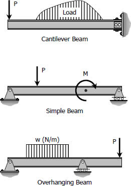
Statically determinate beams are those beams in which the reactions of the supports may be determined by the use of the equations of static equilibrium. The beams shown below are examples of statically determinate beams.
Simple beam, cantilever beam, and overhanging beam

Statically Indeterminate Structures

A structure is statically indeterminate when the static equilibrium equations are insufficient for determining the internal forces and reactions on that structure.


  •  \sum \vec F = 0 :: the vectorial sum of the forces acting on the body equals zero. This translates to
Σ H = 0: the sum of the horizontal components of the forces equals zero;
Σ V = 0: the sum of the vertical components of forces equals zero;
  •  \sum \vec M = 0 : the sum of the moments (about an arbitrary point) of all forces equals zero.

Procedures:
• Obtain equation from static equilibrium
• Compatibility: Obtain equation from deformation
• Apply Hooke's Law
• Solve the unknown

In the beam construction, the four unknown reactions are VA,VB, VC and HA. The equilibrium equations are:
Σ V = 0:
VA − Fv + VB + VC = 0
Σ H = 0:
HA − Fh = 0
Σ MA = 0:
Fv · a − VB · (a + b) - VC · (a + b + c) = 0.
The degree of indeterminacy is taken as the difference between the umber of reactions to the number of equations in static equilibrium that can be applied. In the case of the propped beam shown, there are three reactions R1, R2, and M and only two equations (ΣM = 0 and ΣFv = 0) can be applied, thus the beam is indeterminate to the first degree (3 - 2 = 1).
Propped Beam, Fixed or Restrained Beam, and Continuous Beam

Shear and Moment Diagram

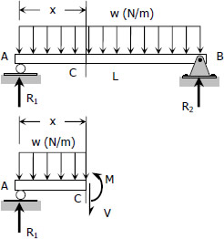
Consider a simple beam shown of length L that carries a uniform load of w (N/m) throughout its length and is held in equilibrium by reactions R1 and R2. Assume that the beam is cut at point C a distance of x from he left support and the portion of the beam to the right of C be removed. The portion removed must then be replaced by vertical shearing force V together with a couple M to hold the left portion of the bar in equilibrium under the action of R1 and wx.


Shear and moment diagrams by shear and moment equations
The couple M is called the resisting moment or moment and the force V is called the resisting shear or shear. The sign of V and M are taken to be positive if they have the senses indicated above.

NOTE:

Write shear and moment equations for the beams in the following problems. In each problem, let x be the distance measured from left end of the beam. Also, draw shear and moment diagrams, specifying values at all change of loading positions and at points of zero shear. Neglect the mass of the beam in each problem.

Unsymmetrical Beams

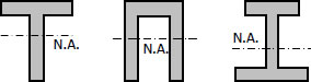
Flexural Stress varies directly linearly with distance from the neutral axis. Thus for a symmetrical section such as wide flange, the compressive and tensile stresses will be the same. This will be desirable if the material is both equally strong in tension and compression. However, there are materials, such as cast iron, which are strong in compression than in tension. It is therefore desirable to use a beam with unsymmetrical cross section giving more area in the compression part making the stronger fiber located at a greater distance from the neutral axis than the weaker fiber. Some of these sections are shown below.
Example of Unsymmetrical Beam-sections
The proportioning of these sections is such that the ratio of the distance of the neutral axis from the outermost fibers in tension and in compression is the same as the ratio of the allowable stresses in tension and in compression. Thus, the allowable stresses are reached simultaneously.

Beam Deflections

• Beams are designed for its rigidity rather than its strength when load is applied, the beams deflection must be kept within the tolerable limit.


• Floor beam carrying plastered ceiling beneath them is restricted to maximum deflection of 1/360 L.

Beam Defections: Double Integration Method

The double integration method is a powerful tool in solving deflection and slope of a beam at any point because we will be able to get the equation of the elastic curve.


For a beam with flexural rigidity EI constant, the differential equation is given by
$ \dfrac{d^2y}{dx^2} = \dfrac{M}{EI} $


Where y represents the vertical deflection; M is the bending moment at a distance x from the conveniently selected origin; E is the modulus of elasticity or Young's modulus; I is the moment of inertia of the beam section; and the product EI is called the flexural rigidity.
Integrating the above equation once will give us dy/dx which is the equation of the slope of elastic curve, usually denoted by ?. Integrating once more (thus, double integration) will result to y which is the equation of the deflection. We can write it into symbols as follows
$ \dfrac{dy}{dx} = \theta = \displaystyle \int \dfrac{M}{EI} + C_1 $
and
$ \displaystyle y = \int \int \dfrac{M}{EI} + C_1x + C_2 $

The constants of integration C1 and C2 can be found by applying appropriate boundary conditions.

The first integration y' yields the slope of the elastic curve and the second integration y gives the deflection of the beam at any distance x. The resulting solution must contain two constants of integration since EI y" = M is of second order. These two constants must be evaluated from known conditions concerning the slope deflection at certain points of the beam. For instance, in the case of a simply supported beam with rigid supports, at x = 0 and x = L, the deflection y = 0, and in locating the point of maximum deflection, we simply set the slope of the elastic curve y' to zero.