Strength of Materials most often refers to various methods of calculating stresses in structural members, such as beams, columns and shafts. The methods that can be employed to predict the response of a structure under loading and its susceptibility to various failure modes may take into account various properties of the materials other than material (yield or ultimate) strength. For example failure in buckling is dependent on material stiffness (Young's Modulus).
The strength of a material is its ability to withstand an applied stress without failure. The applied stress may be tensile,compressive, or shear. Strength of materials is a subject which deals with loads, deformations and the forces acting on the material. A load applied to a mechanical member will induce internal forces within the member called stresses. Those stresses acting on the material cause deformations of the material. Deformation of the material is called strain, while the intensity of the internal forces are called stress. The strength of any material relies on three different type of analytical method: strength, stiffness and stability, where strength refers to the load carrying capacity, stiffness refers to the deformation or elongation, and stability means refers to the ability to maintain its initial configuration. Material yield strength refers to the point on the engineering stress-strain curve (as opposed to true stress-strain curve) beyond which the material experiences deformations that will not be completely reversed upon removal of the loading. The ultimate strength refers to the point on the engineering stress-strain curve corresponding to the stress that produces fracture.
Mechanics
Strength of Materials
Saturday, 7 May 2011
Types of Loadings
Transverse loading - Forces applied perpendicular to the longitudinal axis of a member. Transverse loading causes the member to bend and deflect from its original position, with internal tensile and compressive strains accompanying change in curvature. It also induces shear forces that cause shear deformation of the material and increase the transverse deflection of the member.
Axial loading - The applied forces are collinear with the longitudinal axes of the member. The forces cause the member to either stretch or shorten.
Torsional loading - Twisting action caused by a pair of externally applied equal and oppositely directed couples acting on parallel planes or by a single external couple applied to a member that has one end fixed against rotation.
Loads applied to the beam may consist of a concentrated load (load applied at a point), uniform load, uniformly varying load, or an applied couple or moment. These loads are shown in the following figures.
Stress Terms
Uniaxial stress is expressed by
where F is the force [N] acting on an area A [m2]. The area can be the undeformed area or the deformed area, depending on whether engineering stress or true stress is of interest.
Compressive Stress is the stress state caused by an applied load that acts to reduce the length of the material in the axis of the applied load, in other words the stress state caused by squeezing the material. A simple case of compression is the uniaxial compression induced by the action of opposite, pushing forces. Compressive strength for materials is generally higher than their tensile strength.
Tensile stress is the stress state caused by an applied load that tends to elongate the material in the axis of the applied load, in other words the stress caused by pulling the material. The strength of structures of equal cross sectional area loaded in tension is independent of shape of the cross section. Materials loaded in tension are susceptible to stress concentrations such as material defects or abrupt changes in geometry.
Shear stress is the stress state caused by a pair of opposing forces acting along parallel lines of action through the material, in other words the stress caused by faces of the material sliding relative to one another.
Strength terms
Yield strength is the lowest stress that produces a permanent deformation in a material. In some materials, like aluminium alloys, the point of yielding is hard to define, thus it is usually given as the stress required to cause 0.2% plastic strain. This is called a 0.2% proof stress.
Compressive strength is a limit state of compressive stress that leads to failure in the manner of ductile failure (infinite theoretical yield) or in the manner of brittle failure.
Tensile strength or ultimate tensile strength is a limit state of tensile stress that leads to tensile failure in the manner of ductile failure (yield as the first stage of failure, some hardening in the second stage and breakage after a possible "neck" formation) or in the manner of brittle failure. Tensile strength can be quoted as either true stress or engineering stress.
Fatigue strength is a measure of the strength of a material or a component under cyclic loading, and is usually more difficult to assess than the static strength measures. Fatigue strength is given as stress amplitude or stress range (Δσ = σmax − σmin), usually at zero mean stress, along with the number of cycles to failure.
Impact strength, is the capability of the material to withstand a suddenly applied load and is expressed in terms of energy. Often measured with the Izod impact strength test or Charpy impact test, both of which measure the impact energy required to fracture a sample. Volume, modulus of elasticity, distribution of forces, and yield strength effect the impact strength of a material. In order for a material or object to have a higher impact strength the stresses must be distributed evenly throughout the object. It also must have a large volume with a low modulus of elasticity and a high material yield strength.
Strain terms
Deformation of the material is the change in geometry when stress is applied (in the form of force loading, gravitational field, acceleration, thermal expansion, etc.). Deformation is expressed by the displacement field of the material.
Strain or reduced deformation is a mathematical term to express the trend of the deformation change among the material field. Strain is the deformation per unit length. For uniaxial loading - displacements of a specimen (for example a bar element) it is expressed as the quotient of the displacement and the length of the specimen.
Deflection is a term to describe the magnitude to which a structural element bends under a load.
Stress-strain relations
Elasticity is the ability of a material to return to its previous shape after stress is released. In many materials, the relation between applied stress and the resulting strain is directly proportional (up to a certain limit), and a graph representing those two quantities is a straight line.
Plasticity or plastic deformation is the opposite of elastic deformation and is accepted as unrecoverable strain. Plastic deformation is retained even after the relaxation of the applied stress. Most materials in the linear-elastic category are usually capable of plastic deformation. Brittle materials, like ceramics, do not experience any plastic deformation and will fracture under relatively low stress. Materials such as metals usually experience a small amount of plastic deformation before failure while ductile metals such as copper and lead or polymers will plasticly deform much more.
Plasticity or plastic deformation is the opposite of elastic deformation and is accepted as unrecoverable strain. Plastic deformation is retained even after the relaxation of the applied stress. Most materials in the linear-elastic category are usually capable of plastic deformation. Brittle materials, like ceramics, do not experience any plastic deformation and will fracture under relatively low stress. Materials such as metals usually experience a small amount of plastic deformation before failure while ductile metals such as copper and lead or polymers will plasticly deform much more.
Strength of Materials Formulas
where, σ=normal stress, or tensile stress, pa
P=force applied, N
A=cross-sectional area of the bar, m2
=shearing stress, Pa
As=total area in shear, m2
where,
=tensile or compressive strain, m/m
=total elongation in a bar, m
=original length of the bar, m
Stress is proportional to strain
where,
E=proportionality constant called the elastic modulus or modulus of elasticity or Young’s modulus, Pa
where,
v=Poisson’s ratio
=lateral strain
=axial strain
where,
=change in volume
=original volume
=strain
=Poisson’s ratio
where,
=total elongation in a material which hangs vertically under its own weight
W=weight of the material

where,
=Circumferential or hoop Stress
S=Circumferential or hoop tension
A=Cross-sectional area
=Circumferential strain
E=Young’s modulus

where,
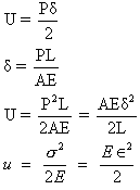
U=total energy stored in the bar or strain energy
P=tensile load
=total elongation in the bar
L=original length of the bar
A=cross-sectional area of the bar
E=Young’s modulus
U=strain energy per unit volume

where,
=normal or circumferential or hoop stress in cylindrical vessel, Pa
=normal or circumferential or hoop stress in spherical vessel, Pa and longitudinal stress around the circumference
P=internal pressure of cylinder, Pa
r=internal radius, m
t=thickness of wall, m


where,
=Shearing Stress, Pa
=Shearing Strain or angular deformation
G=Shear modulus, Pa
E=Young’s modulus, Pa
V=Poisson’s ratio

where,
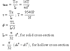
=maximum shearing stress, Pa
r=radius of the section, m
d=diameter of a solid circular shaft, m
=polar moment of inertia of a cross-sectional area, m4
T=resisting torque, N-m
N= rpm of shaft
P=power, kW
L=length of shaft, m
G=shear modulus, Pa
do=outer diameter of hollow shaft, m
di=inner diameter of hollow shaft, m
and

where,
=Ip, polar moment of inertia for thin-walled tubes
r=mean radius
t=wall thickness
Flexure Formula
where,
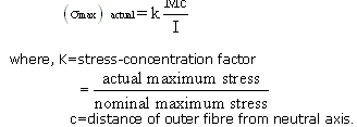
=Stress on any point of cross-section at distance y from the neutral axis
=stress at outer fibre of the beam
c=distance measured from the neutral axis to the most remote fibre of the beam
I=moment of inertia of the cross-sectional area about the centroidal axis

where,
F=Shear force
Q=statistical moment about the neutral axis of the cross-section
b=width
I=moment of inertia of the cross-sectional area about the Centroidal axis.

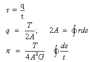
where, =shearing stress at any point of a blue
t=thickness of tube
q=shear flow
T=applied torque
R=distance between a reference point and segment ds
Π=angle of twist of a hollow tube


where, =normal stress
M=bending moment
dA=cross-sectional area of an element
r=distance of curved surface from the centre of curvature
A=cross-sectional area of beam
R=distance of neutral axis from the centre of curvature
R1=distance of centroidal axis from the centre of curvature
(a) Bending of a Beam Supported at Both Ends
(b) Bending of a Beam Fixed at one end
where, d= bending displacement, m
F=force applied, N
I=length of the beam, m
a=width of beam, m
b=thickness of beam, m
Y=Young’s modulus, N/m2
Subscribe to:
Posts (Atom)


